Concept
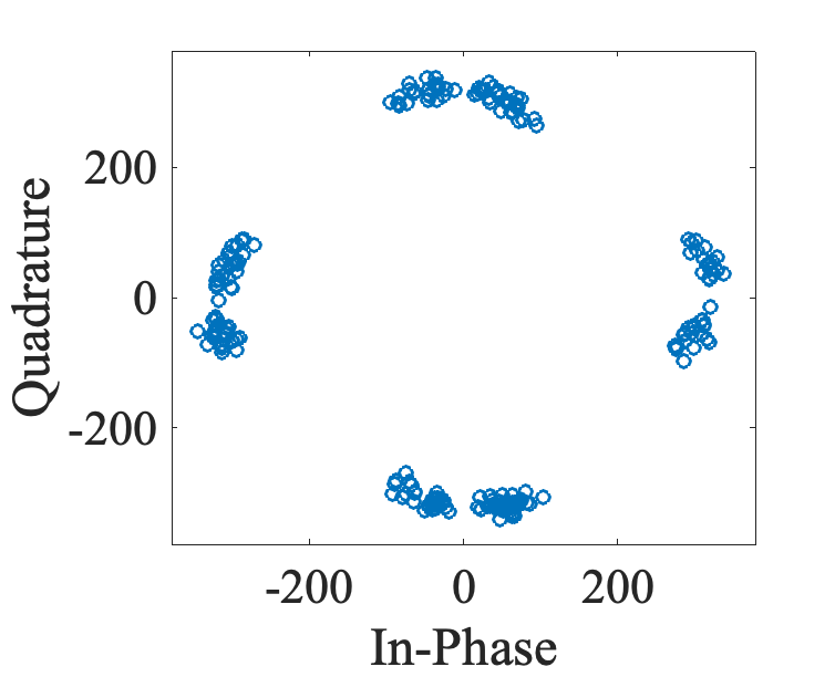
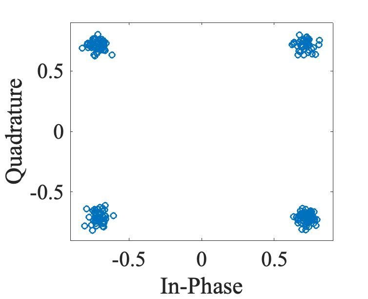
Over the air channel, the signal is modified by interference and noise, and cannot be decoded as-is. Equalization aims at correcting the received signal in order to recover the sent signal before decoding. This is done by estimating channel modifications for each RE grid point, based on pilot signals reception, and by applying inverse modification to received samples. The following Figure shows PDCCH samples before and after channel equalization:
Channel estimation is a vast research topic, and different methods are proposed. Some of those methods are theoretical and cannot be implemented in concrete systems. Some other methods have high computational complexities. Least Square Estimator (LSE) is implemented in the current release which does not take into account channel noise. Noise mitigating estimation methods are planned to be added in future releases.
Channel estimation aims at computing, for each RE, a channel coefficient that represents channel perturbation effects. Correction X, called channel equalization, can be obtained by X = H . Y where Y are received samples and H are channel coefficients.
LSE consists of analysing pilots channel coefficients and propagating values by linear interpolation for non-pilot RE. Different pilots, called DMRS, are used according to the type of the physical channel. The first step is to compute pilots values. Then, channel coefficients are computed, for each i,j (symbol and sub-carrier index) in pilots position indexes:
Linear interpolation is performed in the frequency domain first and then, if needed, in the time domain for recovering channel coefficients at every RE grid position.
Implementation
Channel estimation is defined in lib/phy/libphy/libphy.cpp and can be used like this:
First, pilot coefficients are computed:
Then, the function loops over all symbols and subcarriers, and perofrm linear interpolation:
Where step is the number of subcarriers between studied RE and closest pilot. symbol is the studied symbol, lower_index is the highest lower pilot index and upper_index is the lowest higher pilot index. step_width is the number of subcarriers between two pilots.
If needed, a similar approach is used for time-domain interpolation.